![]()
Introduction
Safety Signs
Controls
Operating Machine
Operating Cutting Units
Replacement Parts
Service Machine Safely
Service Interval Chart
Service Lubrication
Service Engine Gas Units
Service Engine Diesel Units
Engine Warranty Maintenance Statement
Raising and Lowering Engine Cowling
Raising and Lowering Operator Seat
Changing Engine Oil and Filter
Cleaning Oil Cooler Coils and Radiator Cooling Fins
Checking Air Restriction Indicator
Clean Rubber Dust Unloading Valve
Check Radiator Hoses, Air Intake Hose and Clamps
Checking Fuel Filter Sediment Bowl
Cleaning Fuel Filter Sediment Bowl
Checking and Adjusting Alternator Belt
Service Hydraulics & Transmission
Service Cutting Units
Service Electrical
Service Miscellaneous
Troubleshooting
Storing Machine
Assembly
Specifications
Warranty
John Deere Service Literature
John Deere Quality Statement
Copyright© Deere & Company

Service Engine - Diesel Units
Engine Warranty Maintenance Statement
Maintenance, repair, or replacement of the emission control devices and systems on this engine, which are being done at the customers expense, may be performed by any nonroad engine repair establishment or individual. Warranty repairs must be performed by an authorized John Deere dealer.
Avoid Fumes
- If it is necessary to run an engine in an enclosed area, use an exhaust pipe extension to remove the fumes. |
Engine Oil
Use oil viscosity based on the expected air temperature range during the period between oil changes.
The following John Deere oils are preferred:

The following John Deere oils are also recommended:
· TORQ-GARD SUPREME® - SAE 5W30
If John Deere PLUS-50 engine oil and a John Deere oil filter are used, the oil and filter service interval may be extended by 50 hours.
Other oils may be used if above John Deere oils are not available, provided they meet one of the following specifications:
· SAE 15W40 - API Service Classification CG-4,
CF-4, CF or MIL-L-46152B
· SAE 10W30 - API Service Classification CF-4, CF, or Military Specification MIL-L-2104F
· SAE 5W30 - API Service Classification CF
If diesel fuel exceeding 0.5% sulfur content is used, reduce the service interval for engine oil and filter by 50%.
Oils meeting Military Specification MIL-L-46167B may be used as arctic oils.
Raising and Lowering Engine Cowling
IMPORTANT: Avoid damage! To avoid damage to the greens mower, Do Not operate the machine with the cowling in the raised position. |
1. Park greensmower on a hard, level surface.
2. Stop the engine and engage park brake.

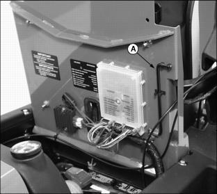
Picture Note: Rear engine cowling on liquid cooled gas model shown.
· Turn button (A) clockwise to unlock cowling.

· Turn button (A) counterclockwise to lock cowling in the lowered position.
Raising and Lowering Operator Seat
Carefully raise and lower the seat to avoid pinching fingers. |
NOTE: Adjust operator seat rearward as far as possible. See Adjusting Seat in the Operating section.
Raising the Seat
· Raise and tilt operator seat forward.

· Remove prop rod (A) secured in stored position under operator seat platform.
· Install prop rod in channel slot (B).
Lowering the Seat
· Remove prop rod from channel slot.
· Secure prop rod in stored position under operator seat platform.
Checking Engine Oil
IMPORTANT: Avoid damage! DO NOT check or add oil while engine is running. To prevent extensive engine wear or damage, always maintain the proper engine oil level. |
1. Park greensmower on a hard, level surface.
2. Stop engine and engage park brake.
IMPORTANT: Avoid damage! Help prevent dirt and other contaminants from entering the oil dipstick tube location. Clean area around dipstick before removing. |
4. Remove dipstick (A). Wipe with a clean cloth.
6. Remove dipstick. Check oil level on dipstick; oil level should be between levels (B) and (C) on the dipstick.
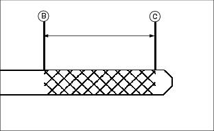
· If oil is low, add oil to bring oil level no higher than level (B) on the dipstick. (See Engine Oil in this section for correct oil application.)
· If oil level is above level (B) on the dipstick, drain to proper level.
Changing Engine Oil and Filter
NOTE: Change engine oil and filter after the first 50 hours of break-in operation.
1. Run engine to warm the oil.
2. Park greensmower on a hard, level surface.
3. Stop engine and engage park brake.
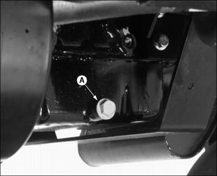
· Place container under oil drain location.
· Remove drain plug (A) located under left side of engine.
· Locate filter under left side of engine.
· Turn filter counterclockwise to remove.
7. Apply a film of clean engine oil on gasket of new filter.
· Turn filter clockwise until gasket makes contact with mounting surface. Tighten 1/2-3/4 turn after gasket contact.
9. Install oil drain plug (A). DO NOT overtighten.
11. Add approximately 2.2 L (2.3 qt.) of engine oil. (See Engine Oil in this section for the correct application.)
· Run engine at a slow "t" throttle speed for approximate two minutes.
· Check area under engine for oil leaks.
15. After approximately two minutes check engine oil level.
IMPORTANT: Avoid damage! Help prevent dirt and other contaminants from entering the oil dipstick tube location. Clean area around dipstick before removing. |
16. Remove dipstick (D). Wipe with a clean cloth.
18. Remove dipstick. Check oil level on dipstick; oil level should be between levels (B) and (C) on the dipstick.
· If oil is low, add oil to bring oil level no higher than level (B) on the dipstick. (See Engine Oil in this section for correct oil application.)
· If oil level is above level (B) on the dipstick, drain to proper level. DO NOT overfill.
20. Close rear engine cowling.
Cleaning Rear Grill Screen
IMPORTANT: Avoid damage! The rear grill screen must be clean to prevent engine from overheating and to allow adequate air intake. |
1. Park greensmower on a hard, level surface.
2. Stop engine and engage park brake.
4. Remove rear grill screen (A) from position behind engine radiator.
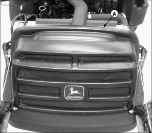
5. Clean screen with compressed air.
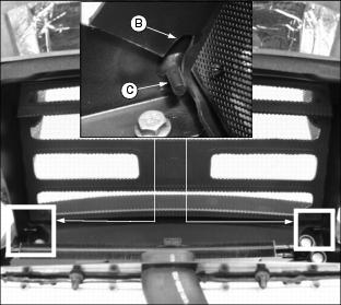
· Install grill screen notches (B) onto each bracket mounting pin (C).
Cleaning Oil Cooler Coils and Radiator Cooling Fins
IMPORTANT: Avoid damage! Oil cooler coils and radiator cooling fins must be clean to prevent overheating. |
1. Park greensmower on a hard, level surface.
2. Stop engine and engage park brake. Allow engine to cool.
4. Remove rear grill screen. (See Cleaning Rear Grill Screen in this section.)
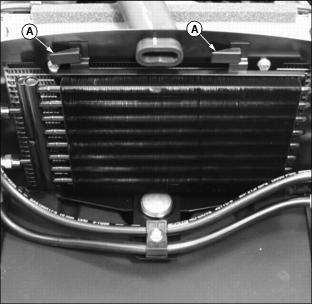
5. Release latches (A) securing oil cooler to the radiator mounting bracket.
· Carefully move oil cooler away from the radiator.
6. Remove dirt and debris from oil cooler coils (C) and radiator fins (D) using compressed air or water.
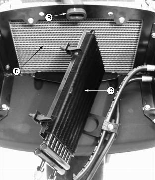
· Check oil cooler coils and radiator fins for damage.
Checking Air Restriction Indicator
1. Park greensmower on a hard, level surface.
2. Stop engine and engage park brake. Allow engine to cool.
NOTE: Indicator will not function correctly if plastic indicator housing is damaged.
4. Locate and check air restriction indicator (A).
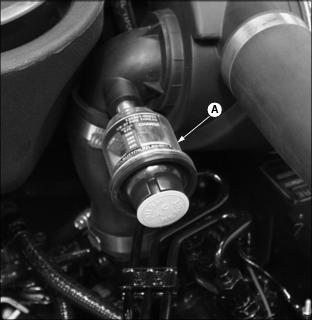
· When yellow plunger (A) inside indicator is visible inside the green zone, no air cleaner service is required.
· When yellow plunger (A) inside indicator is visible inside the red zone, air cleaner requires immediate service. (See Servicing Air Cleaner Element in this section.)
Servicing Air Cleaner Element
IMPORTANT: Avoid damage! DO NOT attempt to clean a primary or secondary air filter element when yellow plunger inside air restriction indicator is visible inside the green zone. |
Primary Air Filter Element
1. Park greensmower on a hard, level surface.
2. Stop engine and engage park brake. Allow engine to cool.
4. Release latches (A) and remove air cleaner canister cover (B).
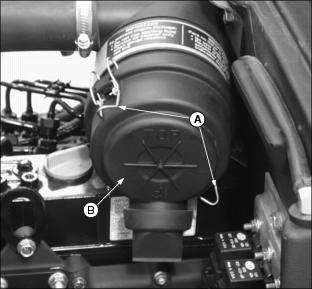
5. Remove and discard primary element (C). Replace with a new primary filter element.

6. Install air cleaner canister cover (B).

· Check instruction molded into canister cover for proper installation.
· Rubber dust unloading valve (D) should be pointed downward when the cover is properly installed.
7. Push reset button (E) on air restriction indicator.

8. Start engine. Allow engine to run approximately one minute at maximum throttle speed.
9. Stop engine. Check air restriction indicator. If yellow plunger inside air restriction indicator is visible inside the red zone, replace secondary air filter element.
Secondary Air Filter Element
1. Remove air cleaner canister cover.
2. Remove primary air filter element.
3. Remove and discard secondary air filter element (F). Replace with a new secondary air filter element.
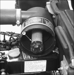
4. Install primary air filter element.
5. Replace air cleaner canister cover.
Clean Rubber Dust Unloading Valve
IMPORTANT: Avoid damage! Never operate engine without air cleaner element and rubber dust unloading valve installed. |
1. Park greensmower on a hard, level surface.
2. Stop engine and engage park brake. Allow engine to cool.
4. Remove dust unloading valve (A) and clean. Replace if damaged.
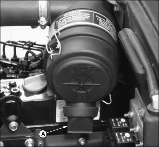
5. Install dust unloading valve.
Check Radiator Hoses, Air Intake Hose and Clamps
1. Park greensmower on a hard, level surface.
2. Stop engine and engage park brake. Allow engine to cool.

· Check hose for cracks or damage.
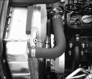
5. Check upper radiator hose (C).
· Check hose for cracks or damage.
6. Check lower radiator hose (D).
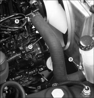
· Check hose for cracks or damage.
Service Cooling System Safely
Engine Coolant
The following John Deere coolant is preferred:
· PRE-DILUTED DIESEL ENGINE ANTI-FREEZE/SUMMER COOLANT (TY16036).
If preferred pre-diluted coolant is not available, the following John Deere concentrate is recommended:
· DIESEL ENGINE ANTI-FREEZE/SUMMER COOLANT CONCENTRATE (TY16034).
These coolants exceed industry specifications: ASTM D5345, D4656, D4985, D3306, and GM6038. They are designed with 5-year or 5000 hour long life formulation (subject to testing annually for conditioner level) for use in all heavy duty diesel engines. These coolants have a coolant conditioner added to help protect against liner pitting and cavitation.
If neither of the above coolants is available, use an ethylene glycol base coolant that meets the following specification:
Check container label before using to be sure it has the appropriate specifications for your machine. Use coolant with conditioner or add conditioner to coolant before using.
IMPORTANT: Avoid damage! To prevent engine damage, DO NOT use pure antifreeze or more than 50% antifreeze in the cooling system. DO NOT mix or add any other type additives to the cooling system. |
If using concentrate, mix approximately 50 percent antifreeze with 50 percent distilled or deionized water before adding to cooling system. This mixture will provide freeze protection to -37 degrees C
(-34 degrees F).
Certain geographical areas may require lower temperature protection. See the label on your antifreeze container or consult your John Deere dealer to obtain the latest information and recommendations.
The preferred antifreeze provides:
· Corrosion-resistant environment within the cooling system.
· Protection against liner pitting and cavitation.
· Compatibility with cooling system hose and seal material.
· Protection during cold and hot weather operations.
Engine Coolant Drain Interval
When using PRE-DILUTED DIESEL ENGINE ANTI-FREEZE/SUMMER COOLANT or DIESEL ENGINE ANTI-FREEZE/SUMMER COOLANT CONCENTRATE (TY16034) coolants, drain and flush the cooling system and refill with fresh coolant mixture every 60 months or 5,000 hours of operation, whichever comes first.
If above John Deere Service coolants are not being used: drain, flush, and refill the cooling system with fresh coolant mixture every 24 months or 600 hours of operation, whichever comes first.
Checking Coolant Level
1. Park greensmower on a hard, level surface.
2. Stop engine and engage park brake. Allow engine to cool.
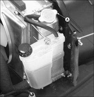
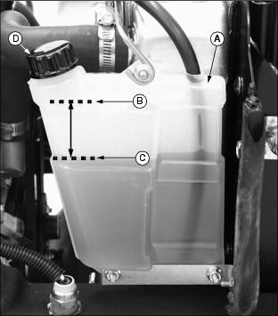
4. Check recovery tank (A) coolant level:
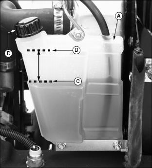
· If engine is warm, coolant level should be between the "H" (HIGH) line (B) and the "L" (LOW) line (C).
· If engine is cold, coolant level should be at the "L" (LOW) line (C) on the recovery tank.
5. Remove recovery tank cap (D) to add coolant.
6. If coolant is low, add specified ratio of antifreeze and water. (See Engine Coolant in this section for the correct application.)
7. Install and tighten recovery tank cap.
8. Clean debris from rear grill screen, oil cooler coils and radiator cooling fins. (See Cleaning Rear Grill Screen and Cleaning Oil Cooler Coils and Radiator Cooling Fins in this section.)
9. Check condition of hoses. Check for leaks or loose connections. (See Check Radiator Hoses, Air Intake Hose and Clamps in this section.)
Draining Cooling System
IMPORTANT: Avoid damage! Help prevent damage to the engine: · DO NOT operate engine without coolant. · DO NOT pour coolant into the radiator when the engine is hot. |
1. Park greensmower on a hard, level surface.
2. Stop engine and engage park brake. Allow engine to cool.
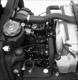
4. Slowly open radiator cap (A) to the first stop to release all pressure.

5. Close radiator cap tightly.
NOTE: A section of plastic or rubber hose can be used to divert fluid away from the greensmower.
6. Open radiator petcock (B). Drain coolant into a pan.
7. When coolant drains from the recovery tank, remove radiator cap.
8. After all coolant has drained, close radiator petcock.
9. Flush cooling system. (See Flushing Cooling System in this section.)
Flushing Cooling System
Turn radiator cap using a thick rag or glove to protect your hand. |
IMPORTANT: Avoid damage! To prevent engine damage: · DO NOT pour water into radiator when engine is hot. · DO NOT operate engine without coolant.
|
1. Fill cooling system with clean water and John Deere Cooling System Cleaner, or John Deere Cooling System Quick Flush or an equivalent. Follow directions on the can.
2. Install and tighten radiator cap (A).
3. Start and run engine until it reaches operating temperature.

· Drain cooling system immediately before rust and dirt settle. (See Draining Cooling System in this section).
Filling Cooling System
1. Fill cooling system. (See Engine Coolant in this section for proper antifreeze application.)
· Certain geographical areas may require lower temperature protection. See the label on your antifreeze container or consult your John Deere distributor to obtain the latest information and recommendations.
· John Deere Cooling System Sealer or its equivalent may be added to the radiator to seal leaks. Do not use any other additives in the cooling system.
2. Install and tighten radiator cap.
3. Run engine until it reaches operating temperature.
5. Check recovery tank (A) coolant level:
· If engine is warm, coolant level should be between the "H" (HIGH) line (B) and the "L" (LOW) line (C).
· If engine is cold, coolant level should be at the "L" (LOW) line (C) on the recovery tank.
6. Remove cap (D) from recovery tank to add coolant if necessary.
7. Check condition of coolant system hoses and clamps. (See Check Radiator Hoses, Air Intake Hose and Clamps in this section.)
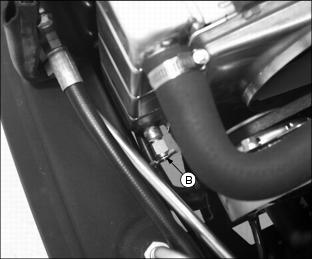
Checking Fuel Filter Sediment Bowl
1. Park greensmower on a hard, level surface.
2. Stop engine and engage park brake. Allow engine to cool.
4. Check for water in sediment bowl (A):

· Orange ring will float on top of the water.
5. If necessary, clean bowl and replace filer. (See Cleaning Fuel Filter Sediment Bowl).
Cleaning Fuel Filter Sediment Bowl
1. Park greensmower on a hard, level surface.
2. Stop engine and engage park brake. Allow engine to cool.
4. Close fuel shut-off valve (A).
5. Turn collar (B) to remove bowl and filter. Discard filter.
7. Install new filter and bowl.
10. Close rear engine cowling.
Using the Fuel Pump Primer
NOTE: The following procedure should be used when the greensmower needs to be restarted after completely running out of fuel.
1. Engage park brake. Allow engine to cool.
2. Check fuel gauge and fill as required. (See Fuel and Filling Fuel Tank in the Service-Miscellaneous section.)
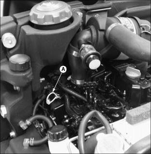
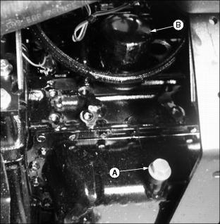
4. Locate fuel priming lever (A) on left side of engine.

NOTE: Make sure fuel shut-off valve is in the "O" (open) position. (See Using Fuel Shut-Off Valve in the Operating section.)
5. Pump fuel priming lever until fuel is visible in the fuel filter sediment bowl (B).
Checking and Adjusting Alternator Belt
Check Belt Tension
1. Park greensmower on a hard, level surface.
2. Stop engine and engage park brake. Allow engine to cool.
· Inspect belt for excessive wear, damage or stretching while in position on the fan, alternator and flywheel sheaves.
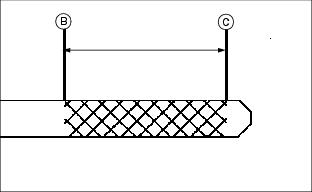
· Apply thumb pressure to the belt approximately halfway between the sheaves. Belt should deflect inward approximately 9.5 mm (3/8 in.).
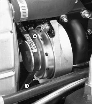
Adjusting Belt Tension
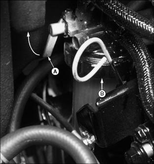
1. Loosen adjustment bolt (B).

Picture Note: Alternator located on right side of engine.
2. Loosen alternator mounting bolt (C).
3. Apply outward pressure to the alternator housing.
4. Tighten alternator adjustment bolt (B) and mounting bolt (C).
· Apply thumb pressure to the belt approximately halfway between the sheaves. Belt should deflect inward approximately 9.5 mm (3/8 in.).
Replacing Alternator Belt
1. Park greensmower on a hard, level surface.
2. Stop engine and engage park brake. Allow engine to cool.
4. Loosen adjustment bolt (A).
Picture Note: Alternator located on right side of engine.
5. Loosen alternator mounting bolt (B).
6. Apply inward pressure to the alternator housing.
7. Remove worn belt from alternator, fan and flywheel sheaves.
9. Apply outward pressure to the alternator housing.
10. Tighten alternator adjustment bolt (A) and mounting bolt (B).

· Apply thumb pressure to the belt (C) approximately halfway between the sheaves. Belt should deflect inward approximately 9.5 mm (3/8 in.).