![]()
Introduction
Safety Signs
Controls
Operating Machine
Operating Mower
Replacement Parts
Service Machine Safely
Service Intervals
Service Lubrication
Service Engine
Service Hydraulics/Transmission
Service Cutting Units
Avoid Injury From Contacting Blades
Removing And Installing Front Roller
Removing And Installing Front Roller (Continued)
Removing And Installing Bed Knife
Adjusting Center Cutting Unit Arm
Service Electrical
Service Miscellaneous
Troubleshooting
Storing Vehicle
Assembly
Specifications
Warranty
John Deere Quality Statement
Copyright© Deere & Company

Service Cutting Units
Avoid Injury From Contacting Blades
Removing And Installing Front Roller
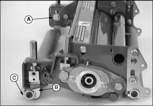
1. Remove cap screw (A) and washer, both ends.
2. Remove front roller brackets (B), both ends, and roller from frame.
3. Remove set screw (C) and nut, both ends.
4. Remove roller from brackets (B).
Removing And Installing Front Roller (Continued)
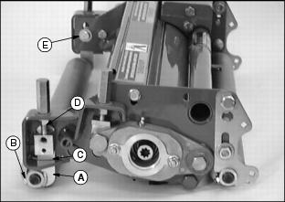
1. Install roller brackets (A) on both ends of the roller.
2. Install set screws and lock nuts (B) loosely in the brackets.
3. Put bracket through slot (C) in frame.
4. Fasten bracket between frame and height-of-cut adjuster bolt (D) using washer and cap screw (E). Install cap screw (E) with head inside frame.
5. Tighten set screws and lock nuts.
6. Adjust roller. (See Adjusting Height-Of-Cut in Operating - Cutting Units section.)
Removing And Installing Bed Knife
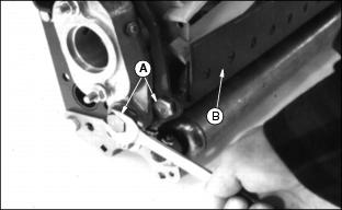
1. Remove two screws (A). Repeat on opposite end.
2. Remove bed knife support, with bed knife (B) attached, from cutting unit housing.
3. Remove and discard screws attaching bed knife to support. Discard bed knife.
4. Remove debris, corrosion, and rust from bottom surface of bed knife support.
5. Install bed knife using new screws. Alternate tightening by starting with center screws.
6. Put bed knife support and bed knife in a suitable grinder and grind until material is removed from the entire top surface of the bed knife lip. (See Grinding The Bed Knife in this section).
7. Raise the reel at least 3 mm (1/8 in.). (See Adjusting Reel-To-Bed Knife in Operating - Cutting Units section.)
NOTE: Bed knife assembly must slip into rear shield locator (C).
8. Install the bed knife support assembly.
9. Adjust reel-to-bed knife. (See Adjusting Reel-To-Bed Knife in Operating - Cutting Units section.)
10. Set height-of-cut. (See Adjusting Height-Of-Cut in Operating - Cutting Units section.)
11. Backlap reel. (Optional Backlapping Kit: see Backlapping Cutting Units in Service - Cutting Units section.)
12. Check height-of-cut and adjust as necessary. (See Adjusting Height-Of-Cut in Operating - Cutting Units section.)
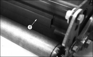
Grinding The Bed Knife
NOTE: Bed knife removed for illustration purposes only.
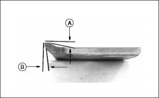
When grinding the bed knife, it is important to have a 5 degree relief angle on the top surface (A) and a 15 degree relief angle on the front surface (B).
Adjusting Center Cutting Unit Arm
NOTE: Pull cutting unit out from left side.
1. Remove center cutting unit.
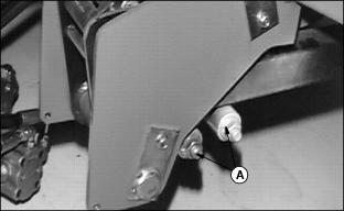
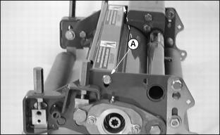
3. Loosen two clamp bolts (A).
4. Start engine and raise lift arms.
NOTE: Photo taken from right side for illustration.
Be sure pin is at the bottom of the V-notch.
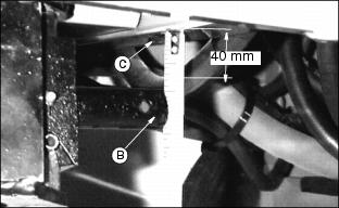
6. Adjust top of pin (B) 40 mm (1-1/2 in.) below the bottom of the frame crossmember (C).

7. Adjust bolt (D) until it touches center cutting unit arm and back off (away from arm) 1/2 turn.
8. Tighten clamp bolts to 129 N·m (95 lb-ft).
Backlapping Cutting Units
NOTE: Backlapping kit is OPTIONAL.
· Disengage GREENS AND TURF CONDITIONER before backlapping. · Avoid injury from rotating blades. Keep hands and feet away while machine is running. |
Backlapping cutting units must be done by TRAINED personnel on a routine basis (25 hours minimum) to prolong reel life, prevent downtime, and provide a consistently sharp cutting action.
NOTE: To maintain sharp edges required on cutting reels:
Adjust cutting reel-to-bed knife. (See Adjusting Reel-To-Bed Knife in Operating - Cutting Units section. The reel must be adjusted to assure a light, even contact over the length of the blade.
IMPORTANT: Avoid damage! To backlap, the reel-to-bed knife clearance should be adjusted to approximately 0.025 mm (0.001 in.) at the ends. |
1. Lower cutting units to the ground.
2. Lock the parking brake. Put mow/transport lever in the TRANSPORT position.
4. Start the engine and set the throttle on LOW idle.
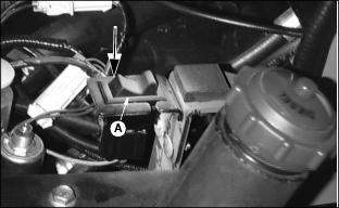
5. Push the service switch (A) down to the backlapping position.
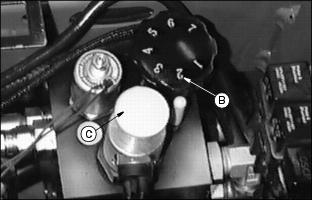
6. Turn the speed control knob (B) clockwise to (2).
7. Move the mow/transport lever to mow position.
NOTE: Cutting units will turn in reverse when knob (C) is pulled up.
8. Put machine in backlapping mode by pulling up on the Forward/Reverse knob (C). Activate the mow button. Cutting units will START.
9. Rotate the speed control knob (B) to adjust the reel speed. Turn the knob clockwise to decrease the reel speed, counterclockwise to increase reel speed.
10. Adjust reel speed slowly enough so grinding compound will not be thrown off during backlapping.
11. Using a long handled brush, carefully apply reel sharpening compound, uniformly, from one end of the reel to the other. Repeat application in opposite direction. Allow unit to continue running backwards until reel is quiet.
12. Periodically disengage cutting units by moving the mow/transport lever to the transport position and shut engine off to visually check blade appearance.
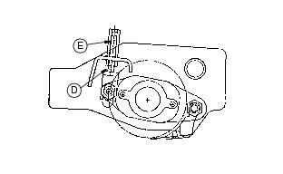
13. Adjust reel-to-bed knife clearance by loosening jam nut (D) and turning adjusting nut (E) and jam nut (D) to proper clearance on both ends. Check for uniform clearance across entire bed knife. If clearance is not uniform, repeat steps 7 through 12 until clearance is uniform across entire bed knife.
14. Use water to thoroughly wash off all reel sharpening compound while reels are turning in reverse.
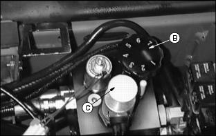
15. Push Forward/Reverse knob (C) in.
16. Shut off engine. Turn speed control knob (B) fully counterclockwise. Return the service switch back to mow position and lower seat.
IMPORTANT: Avoid damage! Do not operate units in the forward direction until reel sharpening compound is washed from the unit. Unless properly washed, the reels can be dulled by the compound. |
Adjusting Cutting Unit Shield
Loosen two bolts (A), one on each side, to adjust cutting unit shield.
Maintain approximately 1 mm (0.04 in.) clearance between the shield and cutting blades.
NOTE: Keeping the shield close to the blades improves the performance of the grass catcher in most conditions.