![]()
Introduction
Safety Signs
Controls
Operating Machine
Operating Mower
Avoid Injury From Contacting Blades
Adjust Rear Roller Mounting Brackets
Operating (Optional) Greens And Turf Conditioner
Adjusting (Optional) Greens And Turf Conditioner
Adjusting (Optional) Rear Roller Powered Brush
Raising/Lowering Cutting Units
Removing And Emptying Grasscatchers
Replacement Parts
Service Machine Safely
Service Intervals
Service Lubrication
Service Engine
Service Hydraulics/Transmission
Service Cutting Units
Service Electrical
Service Miscellaneous
Troubleshooting
Storing Vehicle
Assembly
Specifications
Warranty
John Deere Quality Statement
Copyright© Deere & Company

Operating Mower
Check Ground Conditions
· Clear mowing area of objects that might be thrown. Keep people and pets out of mowing area.
· Study mowing area. Set up safe mowing pattern. Do not mow under conditions where traction or stability is doubtful.
· First, test drive area with CUTTING UNITS OFF but lowered. Slow down when you travel over rough ground.
Avoid Injury From Contacting Blades
BEFORE YOU DISMOUNT TO UNPLUG OR ADJUST CUTTING UNITS:
· DISENGAGE reel drive by moving the mow/transport lever to the TRANSPORT position.
· LOWER cutting units to the ground.
· Wait for reels and all moving parts to STOP.
BLOCKED OR STALLED CUTTING CYLINDERS:
· Keep all parts of the body away from the cutting edges. Residual hydraulic pressure in the system can cause cutting cylinder rotation when the blockage is released.
Adjust Cutting Height
Use three-bolt adjusting gauge bar to:
· Set rear roller parallel to the bed knife cutting edge.
· Adjust the front roller parallel to the rear roller and adjust to desired cutting height.
· Set depth of penetration of blades that make up the GREENS AND TURF CONDITIONER (if so equipped).
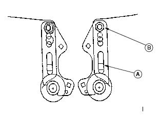
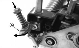
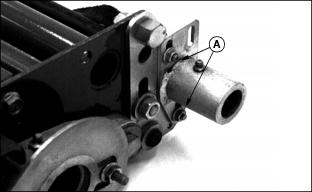
Adjust Rear Roller Mounting Brackets
The rear roller mounting brackets must be adjusted for the height of cut (HOC) range desired.
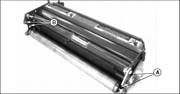
1. Choose TOP or BOTTOM bracket hole (A).
2. Choose TOP, MIDDLE, or BOTTOM frame plate hole (B).
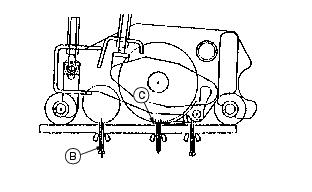
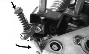
Adjust Rear Roller
NOTE: This procedure is necessary only when the HOC range is changed. Check periodically to be sure roller is level.
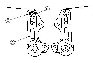
1. Loosen lower rear roller support bolts (A) and remove upper bolt (B) and eccentric (C).
2. Align the upper holes in the roller support with the proper hole in the frame side plate as shown in the table on previous page.
3. Install bolt (B) and nut on the right side and tighten.
4. Install the eccentric (C) and nut on the left side. Do not tighten at this time. The punch mark (D) on the eccentric should be toward the rear of the cutting unit.
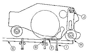
5. Position the gauge bar (E) 51 mm (2 in.) from the right end of bed knife (F).
6. Hook the center gauge screw (G) on the edge of knife and hold the end of the bar against the rear roller (H).
7. Turn the rear screw (I) in until it just touches the bed knife.
8. Move gauge bar to 51 mm (2 in.) from the left end of bed knife.
9. Adjust left end of roller up or down by turning the eccentric bolt (J) until the rear gauge screw just touches bed knife.
10. Tighten all rear roller support hardware and recheck using gauge bar.
Adjust Height-Of-Cut
IMPORTANT: Avoid damage! The rear roller adjustment procedure must be completed before adjusting height of cut. |
1. Set center gauge screw to height of cut desired. Be sure the rear gauge screw is backed out so it does not contact the bed knife.
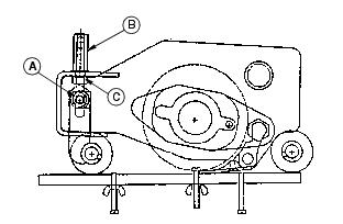
2. Loosen the front roller clamp bolts (A) 1/4-1/2 turn.
3. Position the gauge bar as shown, 51 mm (2 in.) from one end of the bed knife. Hook the center gauge screw on the edge of the knife and hold the end of the bar against the rear roller.
4. Turn top adjuster nut (B) counterclockwise no more than one flat. One flat equals approximately 0.25 mm (0.010 in.) roll movement.
5. Turn jam nut (C) no more than one flat to move roller.
6. Repeat Steps 4 and 5, alternating from side to side to move the roller to the gauge bar.
7. The final turn of nut (C) should move the roller to just touch the gauge bar.
8. Tighten the top adjuster nuts (B) and clamp bolts (A).
9. Using the gauge bar, be sure the roller did not move when adjuster bolt and clamp bolts were tightened.
Adjust Reel-To-Bed Knife
Always wear gloves when manually turning reel. Manually rotating one reel can cause another reel to rotate. |
NOTE: To perform correctly the reel and bed knife must be free from nicks and burrs. (See Backlapping Cutting Units in Service - Cutting Units section.)
1. Loosen top adjuster nut (A) by turning counterclockwise one flat. (One flat equals approximately 0.13 mm (0.005 in.) reel movement).
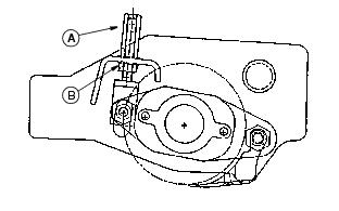
2. Turn jam nut (B) no more than one flat to increase or decrease clearance.
3. Repeat steps 1 and 2 as necessary, alternating from side to side to adjust reel-to-bed knife clearance to 0 to 0.025 mm (0 to 0.001 in.).
4. After the desired clearance is obtained, tighten top adjuster nut.
5. When adjusted correctly, each reel blade should cut a single piece of newspaper held at 90° to the top surface of bed knife along the entire length of the blade.
NOTE: Reel must rotate freely by hand.
Avoid excessive tightening to prevent premature wear or damage to the reel and bed knife.
Operating (Optional) Greens And Turf Conditioner
IMPORTANT: Avoid damage! DO NOT use Greens And Turf Conditioner (GTC) for three days following top dressing. |
The conditioner process involves shallow vertical cutting. The blades are adjusted to cut runners and lift horizontal leaf material. It is important that frequent and thorough observations be performed or stress to the plants may occur. Make adjustments as necessary.
NOTE: It is normal for grass catchers to fill faster when conditioning.
IMPORTANT: Avoid damage! The initial setting should be the same as height-of-cut to prevent damage to the turf. For a deeper cut, set approximately 0.79 mm (.032 in.) below height-of-cut. |
1. Condition greens the first time with blades set the same as height-of-cut. (See Adjust Height-Of-Cut in this section). Closely examine each green and note any inconsistencies or appearance of over-aggressiveness. Decrease GTC penetration if necessary.
2. Check each green 1-2 hours after cutting. Look for any tendency toward a yellow or brown tint. This indicates over-stress.
3. If visible stress is observed, decrease GTC penetration to 0.39 mm. (016 in.).
4. Continue cutting/conditioning at this setting for 3-5 days. Check frequently for stress.
5. If no stress is observed, increase GTC penetration by 0.25 mm (0.010 in.). Check for obvious over-aggressiveness. Observe for 2-3 days, watching for signs of stress.
6. Repeat Step 5, until stress becomes visible. Back off the GTC adjusted penetration by 0.25 mm (0.010 in.).
NOTE: Stress is a cumulative result of many factors such as irrigation, temperature, humidity, chemical application, etc.
Conditioning aggressiveness will require adjustment and monitoring as these factors vary.
Conditioning frequency may also need to be reduced in some cases.
Adjusting (Optional) Greens And Turf Conditioner
1. Press down on GTC adjuster bolts and swing adjuster stops (A) around toward the front of the cutting unit. This is the operating position.
NOTE: Height-Of-Cut must be set prior to setting the Greens And Turf Conditioner.
2. Position cutting unit for making height of cut adjustment. (See Adjusting Height Of Cut in this section).
3. Set GTC adjustment screw (B) on the gauge bar to equal the height of cut, less the penetration desired below height of cut. (See Operating (Optional) Greens And Turf Conditioner in this section).
4. Place preset gauge bar on cutting unit. Hook height of cut screw (C) on bed knife. The ends should rest firmly on the front and rear rollers.
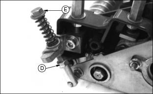
5. Loosen lock nut (D). Repeat on opposite end.
6. Turn adjuster bolt (E) to raise or lower GTC roller. Alternate from side to side until the teeth touch the screw on the gauge bar. Tighten lock nuts.
8. Engage GTC clutch by turning top of engagement knob (F) towards "RUN" to detent position.
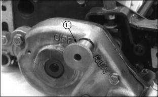
Turn top of engagement knob (F) towards "OFF" to detent position.
10. Move GTC out of operating position by pressing down adjusting bolt, swinging adjuster stop (G) to the side, and releasing adjusting bolt. Repeat on opposite side.
Adjusting (Optional) Rear Roller Powered Brush
1. Loosen four flange nuts (A), two on each side of cutting unit.
NOTE: The brush bristles should just barely touch the full length of the roller.
2. Slide the rear roller powered brush up or down to adjust the roller.
3. Tighten the four flange nuts.
Operating Cutting Units
1. Move mow/transport lever (A) to mow position (B).
2. Move throttle all the way forward to FAST position.
NOTE: Adjust mowing speed if necessary. (See Adjusting Mowing Speed in Service-Hydraulics/Transmission section).
3. Slowly push forward speed control down to begin mowing.
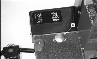
4. Depress mow switch (C) to lower cutting units and start reel rotation.
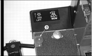
5. Depress lift switch (D) to raise cutting units and stop reel rotation.
IMPORTANT: Avoid damage! The center cutting unit raise and lower is delayed and occurs after the front units begin to raise or lower. |
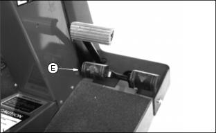
6. Remove foot from speed control lever (E) to stop forward travel.
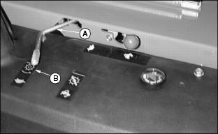
Raising/Lowering Cutting Units
NOTE: Raising and lowering the cutting units can be done MANUALLY.
2. Move mow/transport lever to transport.
4. Get off the machine and lift the seat.
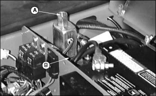
5. Press top button (A) to raise the cutting units. Press bottom button (B) to lower cutting units.
Removing And Emptying Grasscatchers
NOTE: Remove rear grasscatcher from right side of machine.

1. Lift grasscatcher (A) from grasscatcher support frame (B) and empty.
2. Put grasscatchers back on support frame.
Standard Weight Position
NOTE: Weights go on end opposite motors. The weights determine right and left cutting units.
Install weights on right end of two reels and left end of one reel.
Right cutting unit is illustrated.
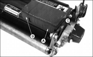
A - Counter Weight: 3.4 kg (7.6 lb)