![]()
Introduction
Safety Signs
Controls
Operating Machine
Operating Mower
Replacement Parts
Service Machine Safely
Service Intervals
Service Lubrication
Service Engine
Service Hydraulics/Transmission
Service Cutting Units
Service Electrical
Service Miscellaneous
Troubleshooting
Storing Vehicle
Assembly
Install Yokes To Cutting Units
Install Bails On Front Cutting Units
Adjust Lift Arm Rollers (Continued)
Install Cutting Units On Greensmower
Install Grass Catcher Frame And Grass Catcher
Specifications
Warranty
John Deere Quality Statement
Copyright© Deere & Company

Assembly
Assemble Greensmower
1. Remove wire from rear wheel clevis.
2. Remove yokes and pivot arms from skid.
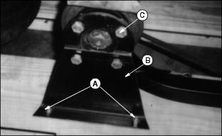
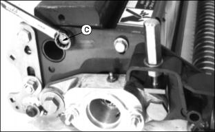
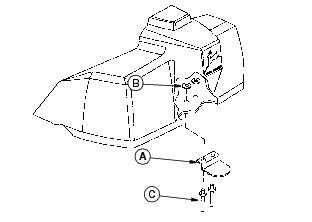
3. Remove bolts and nuts (A) holding shipping bracket (B) to skid.
4. Put jack under axle and raise machine.
5. Remove four lug bolts (C) and shipping bracket.
6. Install wheel using lug bolts.
7. Repeat Steps 5 and 6 on opposite side.
8. Remove bag of parts from under seat platform. (See Raising Seat in Service-Miscellaneous section).
Check Battery

· Check battery voltage, (11.6 Volts, min.).
· If the voltage is below 11.6 Volts, charge the battery. (See Charging The Battery in Service - Electrical section).
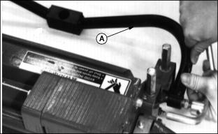
Remove The Machine From Skid

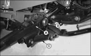
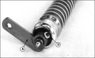
1. Lift seat and push lever (A) down to free-wheeling position.
2. Release parking brake and remove machine from skid.
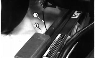
3. Cut shipping wires from front lift cylinder and center lift arm. Cut shipping wires from hoses and motors.
4. Check engine oil and all fluid levels.
5. Push the free-wheeling lever back to "mow" position (B).

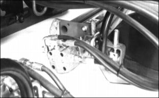
Install Front Lift Arms
1. Install front lift arms (A) using washer and quick-lock pin (B). (C - Lift Cylinder Base)
Picture Note: (A - Front Lift Arms, B - Washer and Quick-Lock Pin)
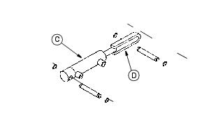
2. Attach lift cylinder base (C) to right arm and cylinder plunger (D) to left arm using snap rings.
Assemble Base Cutting Unit
The cutting units are shipped less the front roller and hydraulic reel motor. The hydraulic reel motor is shipped with the traction unit and the roller is shipped separately.
Install Front Roller
NOTE: Do this for all cutting units.
1. Remove cutting unit and bag of hardware from carton. Discard any packaging materials.
2. Remove roller from carton and inspect for damage
3. Install roller brackets (A) on both ends of the roller.
4. Install setscrews and lock nuts (B) loosely in the brackets.
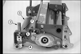
5. Loosen top adjusting nuts (C) on cutting unit frame.
6. Position roller (D) with brackets (A) in alignment with the slots and slide the brackets into the frame.
7. Align the holes in roller brackets with the slots in the frame and the threaded holes in adjusting blocks (E). Install cap screws (F) and washers through the frame and roller brackets. Thread cap screws into adjusting blocks.
NOTE: Center roller from side to side so seals do not rub on roller brackets.
8. Tighten setscrews and lock nuts.
9. Adjust roller. (See Adjusting Height-Of-Cut in Operating - Cutting Unit section.)
Counterweight Location
NOTE: Cutting units are shipped with the three counterweights assembled on the right side. This position is correct for right front and center cutting units.
The left front cutting unit should have the counterweights moved to the left side of the cutting unit.
If installing GREENS AND TURF CONDITIONER or Power Brush Drive, refer to the appropriate kit installation instructions for proper weight locations.
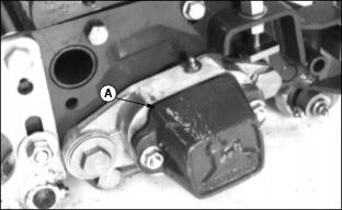
1. Remove the end cap weight (A) from the right side and install on the left end of the cutting unit.
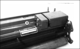
2. Remove M10 x 50 cap screws (B) and small counterweight.
3. Remove M10 x 16 cap screw (C) and large counterweight.
4. Install large counterweight on the left side. Fasten to frame with on M10 x 16 cap screw.
5. Attach small counterweight to large counterweight with two M10 x 50 cap screws.
Install Motor/Reel Coupling
NOTE: Do this for all cutting units.
1. Remove caplug from reel shaft.
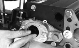
2. Grease inside of coupling (A) and place on the reel shaft.
Install Yokes To Cutting Units
1. Install yokes (A) to cutting units using cap screws (B), bushings (C), and nuts (D).
NOTE: Use matched yokes for front cutting units and remaining yoke for center cutting unit.
Install Bails On Front Cutting Units
NOTE: Product Serial Number plate may interfere when mounting the bail. Grind down one rivet on front cutting units as needed.
Loosen blade shield before putting clamps under cross tube if necessary.
Remove counterweight if it interferes with installation of the bail.
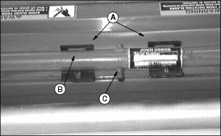
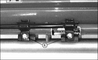
1. Put two clamps (A) under cross tube (B). For approximate bail position, cross pin (C) should be centered between the two clamps.
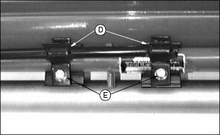
2. Align bail arm brackets (D) and attach to clamps with flanged nuts and carriage bolts (E).
3. Tighten blade shield. Adjust the clearance between the shield and blades to be approximately 1 mm (0.04 in.). Install counterweight if previously removed.
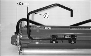
4. Position bail arm (F) approximately 40 mm (1-1/2 in.) from the outside edge of the frame side plate (opposite motor end). Left-hand lift bail shown.
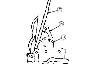
5. Set the 80° bail angle from the top of the counterweight surface (G). Use the template (H) supplied in the machine parts bag. parts bag.
6. Tighten flanged nuts and carriage bolts (E) enough to hold bail in temporary position.
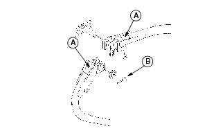
Adjust Lift Arm Rollers
NOTE: Lift arm rollers, one on each lift arm, will be assembled in the TOP position on production machines.
Adjust the lift arm rollers to the TOP or BOTTOM position before installing cutting units.
· Use the lift arm rollers in the TOP position (A) when using cutting units that have SMALL front rollers, 50.8 mm (2 in.) O.D.
Adjust Lift Arm Rollers (Continued)
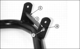
· Remove E-Ring (C) and shaft (D) from roller (E) and lower shaft and roller to the BOTTOM position (B) when using cutting units that have LARGE front rollers, 76.2 mm
(3 in.) O.D.
Install Cutting Units On Greensmower
NOTE: Before mounting cutting units to lift arms, perform the following adjustments to the cutting units:
Rear Roller, Reel-To-Bed Knife, and Height-Of-Cut, (See Operating The Cutting Units section).
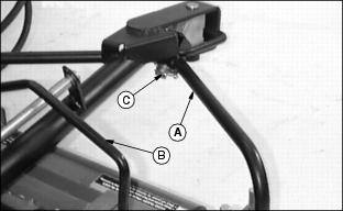
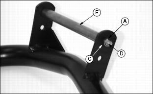
1. Front Lift Arms: Align lift arm pin with the hole in the cutting unit mounting yoke (A). Make sure the bail arm (B) is over roller on lift arm and slide yoke onto lift arm pin. Install washer and fasten with quick-lock pin (C).
NOTE: Slide center cutting unit in on right side of machine.
2. Center lift arm: Mount cutting unit yoke to lift arm pin. Install one washer and quick-lock pin. Attach lift arm cable (D) to the mount pin on rear of cutting unit. Fasten with spring locking pin (E).
3. Install the motors on drive end of cutting units. Make sure splines on motor shafts are lined up with coupling splines.
NOTE: Left hand cutting unit motor is installed on right hand end of cutting unit.
Right hand cutting unit and center unit motors are installed on the left hand end of cutting unit.
4. Check the drop of the front cutting units.
CUTTING UNITS WITH SMALL FRONT ROLLERS,
50.8 mm (2 in.) O.D. Lift arm rollers should be in TOP position. (See Adjust Lift Arm Rollers in this section):
· Raise the units 1/2 way and shut the machine off.
· Manually teeter one side of the lift arms so the cutting unit is approximately 25.4 mm (1 in.) off the floor.
· The rear cutting unit roller should contact the floor flat or with the motor end hitting first within 13 mm (1/2 in.).
· If the non-motor end hits first, loosen the bail and move it away from the motor 6-13 mm (1/4-1/2 in.).
· If the motor end hits more than 13 mm (1/2 in.) before the non-motor end, loosen the bail and move it toward the motor 6-13 mm (1/4-1/2 in.).
· Maintain the bail angle with template. (See Install Bails On Front Cutting Units in this section.) Recheck drop.
CUTTING UNITS WITH LARGE FRONT ROLLERS,
76.2 mm (3 in.) O.D. Lift arm rollers should be in BOTTOM position. (See Adjust Lift Arm Rollers in this section):
· Manually teeter the cutting units as above.
· The rear cutting unit roller should hit the floor flat within 13 mm (1/2 in.).
· If the non-motor end hits more than 13 mm (1/2 in.) before the motor end, loosen the bail and move it away from the motor 13-19 mm (1/2-3/4 in.).
· If the motor end hits more than 13 mm (1/2 in.) before the non-motor end, loosen the bail and move it toward the motor 6-13 mm (1/4-1/2 in.).
· Maintain the bail angle with template. (See Install Bails On Front Cutting Units in this section.) Recheck drop.
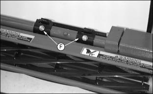
5. Drill two 7 mm (9/32 in.) holes into ONE WALL ONLY of tube. Put two self-tapping flange screws with washers (F) in holes. Tighten to 16.9 N·m (150 in-lb).
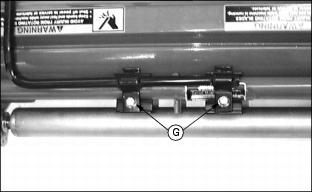
6. Tighten two flanged nuts and carriage bolts (G).
7. Repeat steps 1 through 6 for the other front lift arm and cutting unit.
8. Lubricate grease zerks.(See Service-Lubrication section for specific grease zerk locations and grease recommendations.)
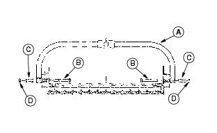
Install Grass Catcher Frame And Grass Catcher
NOTE: Use of retaining clips (A) are optional. Clips are used to prevent the front baskets from bouncing out of the basket supports. Install clips ONLY IF NEEDED.
1. Install clips (A) using washers (B) and rivets (C).
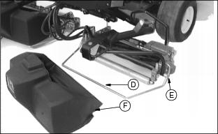
2. Install grasscatcher frame (D) on yoke pins (E).
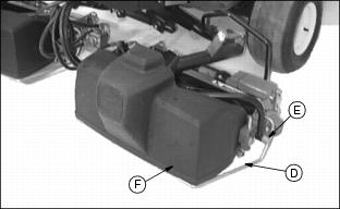
3. Put matching grasscatchers (F) on front cutting units and remaining grasscatcher on center cutting unit.
Checking Tire Pressure
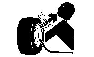
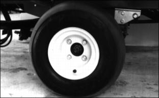
2. Check tire pressure with an accurate gauge.
Correct tire pressure is between 69 to 83 kPa (10 to 12 psi)