![]()
Introduction
Safety Signs
Controls
Operating Machine
Operating Mower Deck
Lawn Care
Replacement Parts
Service Machine Safely
Service Interval Chart
Service Engine
Service Transmission
Service Steering And Brakes
Lubricating The Steering Spindles, Ball Joints, and Tie Rod Ends
Service 48 & 54 Inch Mower Deck
Service 60 Inch Mower Deck
Service Electrical
Service Miscellaneous
Removing 48 & 54 Inch Mower Deck
Removing 60 Inch Mower Deck
Installing 48 & 54 Inch Mower Deck
Installing 60 Inch Mower Deck
Troubleshooting
Storing Machine
Assembly
Specifications
Warranty
John Deere Service Literature
John Deere Quality Statement
Copyright© Deere & Company

Service Steering And Brakes
Grease
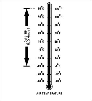
Use the following grease based on the air temperature range. Operating outside of the recommended grease air temperature range may cause premature failures.
IMPORTANT: Avoid damage! DO NOT mix any other greases in this application. DO NOT use any BIO-GREASE in this application. |
The following John Deere grease is preferred:
· TY6341 Multi-Purpose Super Duty High-Temperature EP POLYUREA Grease. NLGI Grade 2.
Other greases may be used if above preferred John Deere grease is not available, provided they meet the following specification:
· John Deere Standard JDM J13E4, NLGI Grade 2.
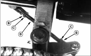
Lubricating The Steering Spindles, Ball Joints, and Tie Rod Ends
1. Lubricate the left and right side rear axle spindle grease fittings (A). (The left rear axle spindle is shown.)
2. Lubricate the center spindle grease fitting (B).

3. Lubricate the front and rear grease fittings of the hydraulic steering cylinder (C and D).
4. Lubricate inner and outer tie rod ends (E).
Lubricating The Pedal Pivot
1. Locate the grease fitting on the differential lock pedal pivot under the left side operator's foot platform.

2. Lubricate the grease fitting using recommended John Deere Grease.
Adjusting The Brake
1. Park the Front Mower safely.
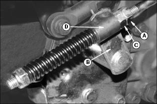
3. Loosen the jam nut (A), and back off several turns.
4. Turn the brake arm (B) clockwise until you feel resistance. Hold the arm there.
5. Turn the adjustment nut (C) on the brake rod until the nut touches the trunnion (D).
6. Tighten the jam nut (A) against adjustment nut (C).
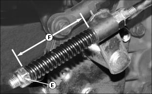
7. Tighten the brake spring adjustment nut (E) until the brake spring length (F) is 75 mm (3 in.).
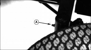
Checking The Toe-In
1. Park the Front Mower safely.
2. Turn the steering wheel as far as it will go to the left.
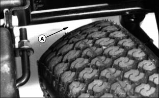
3. Check the clearance (A) between the front of the left tire and the rod. Clearance should be 6-13 mm (1/4-1/2 in.).
4. If not, adjust the left tie-rod.
· Straighten the locking washers (B).
· Turn the tie-rod (D) until clearance in step 4 is correct.
· Flatten washer to nut and tie-rod flats.
5. Turn the steering wheel so the rear wheels are in the straight-ahead position.
6. Measure distance from E to F:
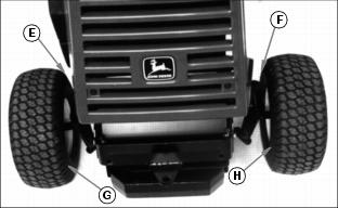
· At the front of the rear wheels.
· At the widest part of the tires.
7. Measure distance from G to H:
· At the rear of the rear wheels.
· At the widest part of the tires.
8. Distance (E) to (F) should be 3 mm (1/8 in.) less than distance (G) and (H).
9. If not, adjust the right side tie rod length until the toe-in is correct. (Do not adjust the left-hand tie rod.).