![]()
Introduction
Safety Signs
Controls
Operating Machine
Operating Mower Deck
Lawn Care
Replacement Parts
Service Machine Safely
Service Interval Chart
Service Engine
Service Transmission
Service Steering And Brakes
Service 48 & 54 Inch Mower Deck
Service 60 Inch Mower Deck
Service Electrical
Checking Battery Electrolyte Level
Replacing an Indicator Light Bulb
Service Miscellaneous
Removing 48 & 54 Inch Mower Deck
Removing 60 Inch Mower Deck
Installing 48 & 54 Inch Mower Deck
Installing 60 Inch Mower Deck
Troubleshooting
Storing Machine
Assembly
Specifications
Warranty
John Deere Service Literature
John Deere Quality Statement
Copyright© Deere & Company

Service Electrical
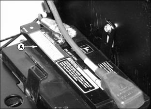
Cleaning Or Replacing Battery


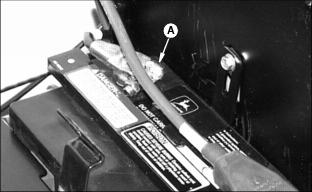
2. Loosen the cable clamp bolt (A) and disconnect the negative cable from the terminal.
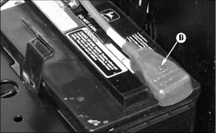
3. Pull the cover (B) away from the positive terminal. Loosen the cable clamp bolt and disconnect the cable.
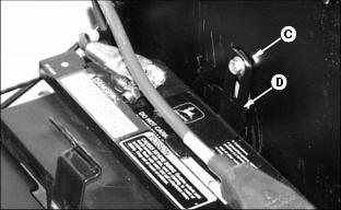
4. Remove the screw (C) and hold-down bracket (D) from the top of the battery.

6. Clean the battery and related parts with a solution of one part baking soda and four parts water. Keep the solution out of the battery cells.
7. Rinse all the parts and let them dry.
· The vent holes in the cap must be open.
· The electrolyte level must be 6 mm (1/4-in.) above the plates.
9. Install the battery. Install the hose in the hole of the battery base and through the hole in the side of the frame. Install the hold-down bracket (D) and screw (C) on the top of the battery.
10. Install the positive cable clamp on the positive (+) battery post and tighten the M8 bolt.

11. Install the cover (B) over the terminal.
12. Install the negative cable clamp on the negative battery post (-) and tighten the M6 bolt (A).
Checking Battery Electrolyte Level
2. Remove battery manifold cap (A).
IMPORTANT: Avoid damage! Do not fill cells to the bottom of the filler neck (B). Electrolyte can overflow when battery is charged and cause damage. |
3. Electrolyte (C) should be 6 mm (1/4 in.) above plates (D).
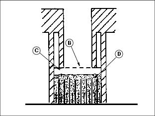
4. Add distilled water if necessary.
5. Install manifold cap. Be sure manifold cap hose is behind positive cable.
Using Booster Battery

1. Connect positive (+) booster cable to booster battery positive (+) post (D).
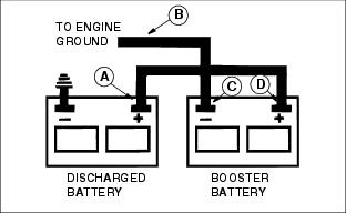
2. Connect the other end of positive (+) booster cable to vehicle battery positive (+) post (A).
3. Connect negative (-) booster cable to booster battery negative (-) post (C).
4. Connect the other end of negative (-) booster cable (B) to engine ground away from battery.
Checking The Indicator Lights

1. Check the operation of the indicator lights:
b. LOOK: All lights should come on:
· Coolant temperature / Glow plug lamp (C)
2. If an indicator does not light, replace the bulb. (See "Replacing an Indicator Light Bulb" in this section.)
3. If the new bulb does not light or no indicators work, see your John Deere dealer.
Replacing an Indicator Light Bulb
2. Carefully pry the back cover (B) loose.

3. Pull the burned out bulb (C) straight out: Do not twist it.
4. Push the new bulb straight in.
5. Install the cover. Fasten it with the screw.
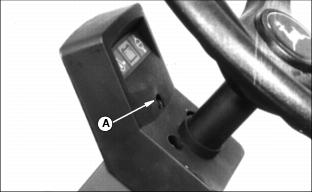
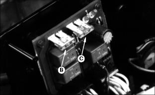
Replacing The Fuses
1. Lift the seat to the highest position.

2. Pull the fuse cover (A) off.
3. Replace the burned-out fuse with a 15-amp fuse only:
· (B)-Fuse for controls and seat safety switch circuits.
· (C)-Fuse for headlight circuit.
4. Pull out the burned-out fuse. Push in a new fuse.
Checking The Fusible Links

· When none of the electrical parts on the Front Mower work OR
· When all circuits except the starting circuit work.
See you John Deere Dealer or technical manual for fusible link testing.