![]()
Introduction
Safety Signs
Controls
Operating Machine
Operating Mower Deck
Avoid Injury From Contacting Blades
Adjusting Cutting Height And Gauge Wheel (48 and 54 Inch Deck)
Adjusting Cutting Height - 60 Inch 7 Iron Deck (S.N. 015001- )
Adjusting Cutting Height (60 Inch Deck) (S.N. -015000)
Checking The Mower Deck Side-To-Side Level
Adjusting Mower Deck Side-to-Side Level (48 and 54 Inch Deck)
Adjusting Mower Deck Side-to-Side Level (60 Inch - 7 Iron Deck) (S.N. 015001-)
Adjusting Mower Deck Side-to-Side Level (60 Inch Deck) (S.N. -015000)
Checking Mower Deck Front-To-Rear Level
Adjusting Mower Level Front-To-Rear (48 and 54 Inch Deck)
Adjusting Mower Level Front-To-Rear (60 Inch - 7 Iron Deck) (S.N. 015001- )
Adjusting Mower Level Front-To-Rear (60 Inch Deck) (S.N. -015000)
Lawn Care
Replacement Parts
Service Machine Safely
Service Interval Chart
Service Engine
Service Transmission
Service Steering And Brakes
Service 48 & 54 Inch Mower Deck
Service 60 Inch Mower Deck
Service Electrical
Service Miscellaneous
Removing 48 & 54 Inch Mower Deck
Removing 60 Inch Mower Deck
Installing 48 & 54 Inch Mower Deck
Installing 60 Inch Mower Deck
Troubleshooting
Storing Machine
Assembly
Specifications
Warranty
John Deere Service Literature
John Deere Quality Statement
Copyright© Deere & Company

Operating Mower Deck
Check Ground Conditions
· Clear mowing area of objects that might be thrown. Keep people and pets out of mowing area.
· Study mowing area. Set up safe mowing pattern. Do not mow under conditions where traction or stability is doubtful.
· First, test drive area with PTO switch DISENGAGED and mower lowered. Slow down when you travel over rough ground.
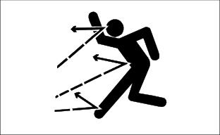
Avoid Injury From Contacting Blades
Before you dismount to unplug or adjust mower:
· DISENGAGE PTO switch to stop mower blades.
· Wait for mower blades to STOP.
· Keep hands, feet and clothing away from mower deck when engine is running.
· DISENGAGE PTO switch to stop mower blades when you are not using mower.
Adjusting Cutting Height And Gauge Wheel (48 and 54 Inch Deck)
NOTE: The pointer (A) does not show the cutting height on the decal (B). The numbers 1-4 are for reference only.

1. Turn the crank (C) to put the mower at the desired cutting height-from 25-100 mm (1-4 in). One turn of the crank will raise or lower the mower approximately 6 mm (1/4 in). Leave the crank at the bottom of a turn.
2. Cut a short strip of grass. For best results, measure the height of the grass at several places in the strip.
NOTE: When the mower is set at the desired cutting height, note the pointer number on the decal. Use this number as a reference to set the cutting height in the future.
3. Remove the ring (D) and drilled pin (E) from the wheel arm.

· For normal operation: Adjust the wheel to 6 mm (1/4 in.) above the ground.
· For rough or uneven ground: If scalping is a problem, try running the wheel on the ground.
5. Install the drilled pin and the ring.
Adjusting Cutting Height - 60 Inch 7 Iron Deck (S.N. 015001- )
1. Park the Front Mower safely.
· Front Mower drive tires: 60 kPa (8 psi)
· Front Mower rear tires: 100 kPa (15 psi)
· Mower Deck caster tires: 310 kPa (45 psi)
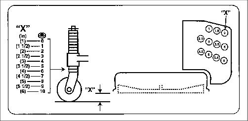
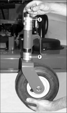
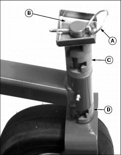
5. Use the illustration below, or the decal on the front of the mower deck, to select a desired cutting height.
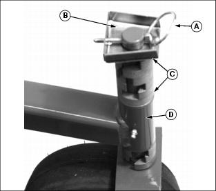
6. Support the caster wheel with one hand while removing quick-lock pin (A) and spacer guard (B).
7. Remove the spacers (C) from the top of the caster pivot shaft.
8. Lower the the caster pivot shaft out of the deck support bracket (D).
9. Use the chart below to determine the number of spacers to use on the caster pivot shaft to obtain the desired cutting height. Install the spacers on the shaft.
10. Install the caster pivot shaft up into the deck support bracket.
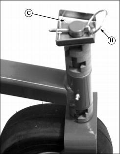
11. Support the caster wheel while installing the remaining spacers on the top of the caster bracket shaft.
12. Install the spacer guard (G) onto the caster pivot shaft as shown. Rotate the guard so that the quick lock pin (H) can be installed with the pin facing the rear.
13. Remove the retaining ring (I) holding the rear hanger pin (J) to the adjustment plate (K). Place the rear hanger pin in the hole that matches the height selected for the front caster wheels, and install the retaining ring.

14. Start engine and lower mower deck. Stop engine.
15. Check that pin (L) is installed through the gauge wheel arm and deck bracket. Secure pin with retaining ring (I).
16. Measure the distance from the bottom of the gauge wheel to the ground.
17. Adjust the gauge wheels as follows:

· For normal operations, adjust the wheel to 6 mm ( in.) above the ground.
· For rough or uneven ground, or if scalping is a problem, try running the wheel on the ground.
18. Remove retaining ring (J) and drilled pin (K) from gauge wheel bracket.
19. Raise or lower wheel and install drilled pin in nearest hole to correct height.
21. Check mower deck leveling, front-to-rear, and side-to-side.
Adjusting Cutting Height (60 Inch Deck) (S.N. -015000)
NOTE: The numbers marked on the mower deck decal (C) may not be actual cutting height, unless mower deck cutting is calibrated to match decal.
1. Park the Front Mower safely.
· Front Mower drive tires: 60 kPa (8 psi)
· Front Mower rear tires: 100 kPa (15 psi)
· Mower Deck caster tires: 310 kPa (45 psi)
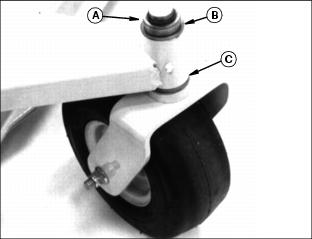
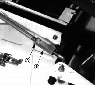
5. Pull out latch levers (A and B) until handles can be turned to face upward.

Picture Note: Rear handle (A) is shown unlatched, front handle (B) is latched in the #4 hole.
6. Using the decal (C) on the front of the mower deck, select a hole in the height adjustment plate (D) that corresponds to the desired cutting height.

7. Grab the front handle (E) and raise or lower the caster wheels until front or rear latch lever (A or B) align with the selected hole.
8. Turn the latch lever handle to allow it to drop into the selected hole.
9. Check the decal on the front of the mower deck to find the hole on the rear hanger bracket that matches the height chosen for the front caster wheels.

10. Remove the retaining ring (F) holding the rear hanger pin (G) to the adjustment plate (H). Place the rear hanger pin in the hole that matches the height selected for the front caster wheels, and install the retaining ring.
11. Start engine and lower mower deck. Stop engine.
12. Check the latch pin (I) for the gauge wheel assembly is locked into hole in deck bracket.
13. Measure the distance from the bottom of the gauge wheel to the ground.
14. Adjust the gauge wheels as follows:

· For normal operations, adjust the wheel to 6 mm ( in.) above the ground.
· For rough or uneven ground, or if scalping is a problem, try running the wheel on the ground.
15. Remove retaining ring (J) and drilled pin (K) from gauge wheel bracket.
16. Raise or lower wheel and install drilled pin in nearest hole to correct height.
18. Check mower deck leveling, front-to-rear, and side-to-side.
Checking The Mower Deck Side-To-Side Level
1. Park the Front Mower safely.
· Front Mower drive tires: 60 kPa (8 psi)
· Front Mower rear tires: 100 kPa (15 psi)
· Mower Deck Caster Wheel tires: 310 kPa (45 psi)
3. Set the mower at the desired cutting height.
4. For 60 Inch mower deck, check that front caster wheel adjuster, and rear hanger adjustment are all set to the same adjustment height. (See "Adjusting Mower Deck Cutting Height" in this section.)
5. Turn the blades parallel to the front mower's axle.
NOTE: Use a short ruler or leveling gauge (B) for measuring.
6. Lift the mower chute. Measure from the right blade tip to the floor (A).

7. Measure from the left blade tip to the floor.
8. Dimension (A) on both blades must not differ by more than 3mm (1/8 in). If the difference is greater, adjust the level.
Adjusting Mower Deck Side-to-Side Level (48 and 54 Inch Deck)
1. Raise and block one side of the mower-about 150 mm (6 in).
3. Remove the wheel from the mower.
4. Put the top washer(s) (B) in the bottom position (C) to raise one side of the mower, OR put the bottom washer(s) in the top position to lower the mower. Keep the thin thrust washer between washer(s) (C) and the bottom bushing.
Adjusting Mower Deck Side-to-Side Level (60 Inch - 7 Iron Deck) (S.N. 015001-)
1. Start the engine and raise the mower deck. Stop engine.
2. Hold caster wheel and remove quick lock pin (A) from top of caster pivot shaft.
· To raise deck, move spacers from top position (C) to bottom position (D).
· To lower deck, move spacers from bottom position to top postion.
5. Install the spacer guard and quick lock pin with the pin facing rearward, as shown.
6. Start engine and lower mower deck. Stop engine.
7. Check blade height side-to-side. If deck needs more adjustment, perform the following:

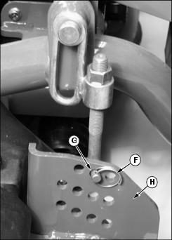
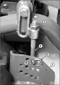
a. Loosen lock nut (E) from rear deck hanger (F).
b. Remove retaining ring (G) holding rear hanger pin (H) to the adjustment plate (I).
c. Lift deck slightly by hand and pull pin (H) from plate (I).
d. Screw rear hanger up or down to adjust rear deck height.
e. Insert pin back into same hole it was removed from and secure with retainer ring. Tighten lock nut.
f. Check blade height side-to-side and adjust, if necessary.
Adjusting Mower Deck Side-to-Side Level (60 Inch Deck) (S.N. -015000)
1. Start engine and raise mower deck about 150 mm (6 in.) off ground. Stop engine.
2. Hold caster wheel bracket (A) and remove external snap ring (B) from top of pivot.

· To raise deck, move spacers from top position (C) to bottom position (D).
· To lower deck, move spacers from bottom position to top postion
4. Install the external snap ring.
5. Start engine and lower mower deck. Stop engine.
6. Check blade height side-to-side. If deck needs more adjustment, perform the following:
a. Loosen lock nut (E) from rear deck hanger (F).
b. Remove retaining ring (G) holding rear hanger pin (H) to the adjustment plate (I).
c. Lift deck slightly by hand and pull pin (H) from plate (I).
d. Screw rear hanger up or down to adjust rear deck height.
e. Insert pin back into same hole it was removed from and secure with retainer ring. Tighten lock nut.
f. Check blade height side-to-side and adjust, if necessary.
Checking Mower Deck Front-To-Rear Level
1. Park the Front Mower safely.
· Front Mower drive tires: 60 kPa (8 psi)
· Front Mower rear tires: 100 kPa (15 psi)
· Mower Deck caster tires: 310 kPa (45 psi)
3. Check that front caster wheel adjuster, and rear deck hanger adjustment are all set to the same adjustment height. (See "Adjusting Cutting Height" in this section.)
4. Lift discharge chute. Rotate the right blade by hand until it points front-to-rear.

5. Using a short ruler or blade leveling guide (A), measure cutting height from the bottom of the front blade cutting edge to the ground.
6. Turn the right blade 180 degrees. Measure cutting height from the bottom of the same cutting edge as used in step 5, (now pointing to rear).
7. Dimension (B) should be 3-6 mm (1/8-1/4 in.) greater with blade pointed rearward than when pointed forward. (Blade higher in rear).
Adjusting Mower Level Front-To-Rear (48 and 54 Inch Deck)
NOTE: Make adjustment to both sides of deck as needed.
2. Turn the turnbuckle (B) to raise or lower the rear of the mower.
3. When the adjustment is correct, tighten the nut (A).
Adjusting Mower Level Front-To-Rear (60 Inch - 7 Iron Deck) (S.N. 015001- )
NOTE: Adjust front caster wheel height and rear deck hangers an equal amount in opposite directions to keep the overall cutting height from changing.
1. Start engine and raise mower deck. Stop engine.
2. Hold caster wheel and remove quick lock pin (A) from top of caster pivot shaft.

· To raise deck, move spacers from top position (C) to bottom position (D).
· To lower deck, move spacers from bottom position to top postion
5. Install the spacer guard and quick lock pin with the pin facing rearward, as shown.
6. Start engine and lower mower deck. Stop engine.

7. Loosen locknut (G) on rear deck hanger.
8. Remove retainer ring (H) from hanger pin (I).
9. Lift deck slightly by hand and pull hanger pin from adjustment plate (J).
10. Turn adjustment hanger up or down to raise or lower rear of deck. Tighten lock nut.
11. Recheck blade height front-to-rear. Check blade height side-to side. (See "Leveling Mower Deck Side-to Side" in this section.)
Adjusting Mower Level Front-To-Rear (60 Inch Deck) (S.N. -015000)
NOTE: Adjust front caster wheel height and rear deck hangers an equal amount in opposite directions to keep the overall cutting height from changing.
1. Start engine and raise mower deck about 150 mm (6 in.) off of ground. Stop engine.
2. Hold caster wheel (C), and remove external snap ring (D) from top of pivot.
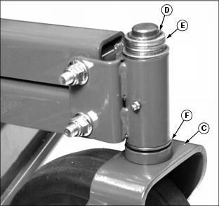
· To raise deck, move spacers from top position (E) to bottom position (F).
· To lower deck, move spacers from bottom position to top position.
4. Install the external snap ring.
5. Start engine and lower mower deck. Stop engine.

6. Loosen locknut (G) on rear deck hanger.
7. Remove retainer ring (H) from hanger pin (I).
8. Lift deck slightly by hand and pull hanger pin from adjustment plate (J).
9. Turn adjustment hanger up or down to raise or lower rear of deck. Tighten lock nut.
10. Recheck blade height front-to-rear. Check blade height side-to side. (See "Leveling Mower Deck Side-to Side" in this section.)