![]()
Introduction
Safety Signs
Controls
Operating Machine
Operating Mower Deck
Lawn Care
Replacement Parts
Service Machine Safely
Service Interval Chart
Service Engine
Service Transmission
Service Steering And Brakes
Service 48 & 54 Inch Mower Deck
Service 60 Inch Mower Deck
Service Electrical
Service Miscellaneous
Removing 48 & 54 Inch Mower Deck
Removing 60 Inch Mower Deck
Installing 48 & 54 Inch Mower Deck
Installing 60 Inch Mower Deck
Troubleshooting
Storing Machine
Assembly
Remove Front Mower Shipping Straps
Fasten The Driveline To The Mower Gearbox Shaft
Assemble 60 Inch Mower Deck (S.N.-011682)
Specifications
Warranty
John Deere Service Literature
John Deere Quality Statement
Copyright© Deere & Company

Assembly
Remove Front Mower Shipping Straps
1. Carefully cut and discard the metal banding strap that secures the rear bumper to the crate.
2. Remove and discard the two lag bolts that secure the shipping brackets to the 2 x 4 at the front of the machine.
3. Remove the four tie straps that secure the two rear wheel assemblies to the side of the crate.
5. Remove and discard the two shipping brackets that secure the machine to the 2 x4.
6. Discard the four bolts and locknuts from the two shipping brackets.
Installing Wheels and Tires
1. Jack or hoist rear axle of Front Mower up from pallet enough to install rear tires.
2. Remove and discard the protective cover from each of the two axle spindles.
3. Install rear wheel on axle spindle with valve stem (A) facing out.

4. Locate external snap ring (B) from bag of parts and install in groove on rear axle.
5. Install molded axle cover (C) over end of axle shaft and tap with hammer until snapped in place.
6. Repeat steps 3-5 for other side of Front Mower.
7. Lower rear of Front Mower to ground.
8. Raise front drive axle up from pallet and install front tire onto axle flange with valve stem facing out. Use a torque wrench to tighten bolts to 80 N·m (60 lb-ft). Repeat for other side.
NOTE: Check wheel bolt torque after each use of the Front Mower for the first 100 hours of operation.
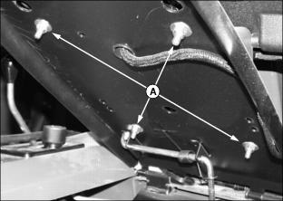
Install The Seat
1. Lock the seat platform in the highest position.

2. Set the operator's seat onto the seat platform lining up the four studs on the bottom of the seat to the holes in the platform.
3. Fasten the seat to the seat platform with four flat washers and locknuts (A).
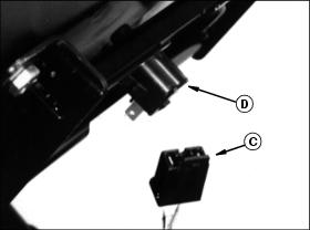
4. Connect the wiring harness (C) to the male terminals of the operator presence switch (D) on the bottom of the seat.
Install The Steering Wheel
1. Put the rear wheels in the straight-ahead position.
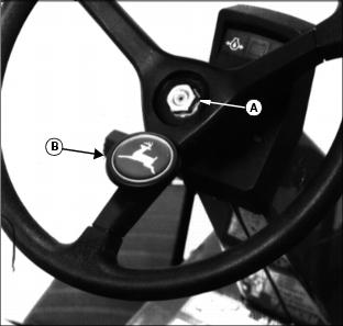
2. Install the black plastic spacer on the steering wheel shaft.
3. Put the steering wheel on the shaft with one spoke pointing to the rear.
4. Install and tighten the nut (A).
5. Push the cover with insert (B) onto the steering wheel with the leaping deer in the upright position.
Fasten The Driveline To The Mower Gearbox Shaft
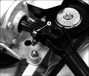
1. Line up the holes in the driveline coupler with the groove in the mower gearbox shaft.
2. Install the two M10 x 50 bolts (A) and lock nuts as shown-one from each side. Tighten the nuts to 75 N·m (55 lb-ft).
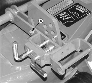
Assemble 60 Inch Mower Deck (S.N.-011682)
1. Loosen cap screw and nut (A) on 60 inch mower deck height adjustment handle to allow handle to slide freely up and down in adjustment plate.