![]()
Introduction
Safety Signs
Controls
Operating Machine
Operating Mower Deck
Lawn Care
Replacement Parts
Service Machine Safely
Service Interval Chart
Service Engine
Service Transmission
Service Steering And Brakes
Service 48 & 54 Inch Mower Deck
Service 60 Inch Mower Deck
Service Electrical
Service Miscellaneous
Removing 48 & 54 Inch Mower Deck
Removing 60 Inch Mower Deck
Installing 48 & 54 Inch Mower Deck
Installing 60 Inch Mower Deck
Troubleshooting
Storing Machine
Assembly
Specifications
Warranty
John Deere Service Literature
John Deere Quality Statement
Copyright© Deere & Company

Removing 48 & 54 Inch Mower Deck
Removing Mower
2. Lift the seat platform to the highest position.

3. Disconnect the mower deck driveline (A) from the vehicle's PTO shaft (B) by pulling the coupler ring (C) forward and pulling forward on the driveshaft.
4. Turn the crank clockwise to raise the mower to its highest position.
5. Lower the rear mower wheel to the lowest position.
6. Turn the crank counterclockwise to lower the mower until the rear mower wheel contacts the ground.
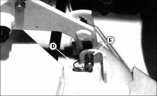
7. Remove the ring (D) and the drilled pin (E) from the rear of the mower on each side.
NOTE: Do not rotate the link (F) when removing bracket (G), or the mower deck leveling will be changed.
8. Pull the bracket (G) off the push arm shaft (H). Lay the bracket off to the side as shown.

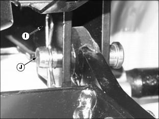
9. Pull out the spring pins (I) and (J) which fasten the lift frame to the push arms, as follows:

· Turn the crank counterclockwise to lower the deck and raise the front of the lift frame. This will help release the pressure on the rear spring pins (I).
· Pull the rear spring pin (I) out on each side until you can lock the latch pin (J) into the slot as shown.
· Turn the crank clockwise and lower the mower frame to release pressure on the front spring pins (J).
· Pull the front spring pin (J) on each side until you can lock the latch pin (K) into the slot as shown.
10. Raise the left and right side lift arms (L) out of the mower deck frame.
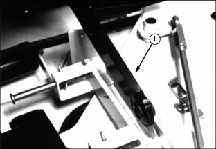
11. Lift the mower deck driveshaft up to clear Front Mower transaxle, and pull the mower deck away from the Front Mower.
· Fasten the rear brackets, drilled pins, and rings on the mower.
· Release the four spring pins from the latched position.
13. Lower the seat platform. Raise lift arms before moving or driving Front Mower.
Storing The Mower Deck
1. Remove the belt shields. Clean the top and the underside of the mower.
2. Check the blades. If necessary, remove, sharpen, and balance the blades.
3. Replace badly worn or damaged parts.
4. Apply paint to areas that need it to prevent rust.
5. Lubricate the grease points.
6. Use a spring puller to remove the end of the belt tension spring from its bracket.
Removing Lift Arms
1. Remove mower deck from lift arms. (See "Removing Mower Deck" in this section.)

2. Park Front Mower on level surface, park brake ON, lift arms LOWERED, engine OFF.
3. Remove spring pin (A). Hold weight of lift arms up slightly while removing drilled pin (B) from lift cylinder. Set ends of lift arms down on ground.
4. Remove cotter key (C) and castle nut (D) holding right lift arm to Front Mower bracket (E).

5. Remove two Nylock hex nuts (F) and cap screws (G) from left lift arm.

6. Remove bracket and rod (H) from Front Mower. Lower right lift arm to ground.
7. Remove spring pin (I) holding left lift arm pivot pin (J) in place. Remove pivot pin and remove lift arm assembly from Front Mower.
See "Installing Lift Arms" in the "Installing 48 & 54 Inch Mower Deck" section for installation.