![]()
Introduction
Safety Signs
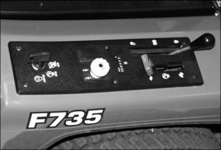
Controls
Operating Machine
Operating Mower Deck
Lawn Care
Replacement Parts
Service Machine Safely
Service Interval Chart
Service Engine
Service Transmission
Service Steering And Brakes
Service 48 & 54 Inch Mower Deck
Service 60 Inch Mower Deck
Service Electrical
Service Miscellaneous
Checking Mower Blade Stop Time
Removing 48 & 54 Inch Mower Deck
Removing 60 Inch Mower Deck
Installing 48 & 54 Inch Mower Deck
Installing 60 Inch Mower Deck
Troubleshooting
Storing Machine
Assembly
Specifications
Warranty
John Deere Service Literature
John Deere Quality Statement
Copyright© Deere & Company

Service Miscellaneous
Checking Tire Pressure

2. Check tire pressure with an accurate gauge.
3. Add or remove air, if necessary:
Diesel Fuel Specifications
In general, diesel fuels are blended to satisfy the low air temperature requirements of the geographical area in which they are sold.
Diesel fuel is usually specified to ASTM D975 and sold as either Grade 1 for cold air temperatures or Grade 2 for warm air temperatures.
If diesel fuels being supplied in your area DO NOT meet any of the above specifications, use diesel fuels with the following equivalent properties:
· Cetane Number 40 (minimum). A cetane number greater than 50 is preferred, especially for air temperatures below -20°C (-4°F) or elevations above 1500 m (5000 ft).
· Cold Filter Plugging Point (CFPP). The temperature at which diesel fuel begins to cloud or jell. Use diesel fuels with a CFPP which is at least 5°C (9°F) below the expected low air temperature.
· Sulfur Content of 0.05% (maximum). Diesel fuels for highway use in the United States now require sulfur content to be less than 0.05%. If diesel fuel being used has a sulfur content greater than 0.5%, reduce the service interval for engine oil and filter by 50%.
Bio-Diesel Fuels with bio-degradable properties that meet specification DIN 51606 or equivalent may be used.
Consult your local diesel fuel distributor for properties of the diesel fuel available in your area.
Lubricity
Diesel fuel must have adequate lubricity to ensure proper operation and durability of fuel injection system components. Fuel lubricity should pass a minimum of 3300 gram load level as measured by the BOCLE scuffing test.
Fuel Storage
It is recommended that diesel fuel be stored only in a clean, approved polyethylene plastic container without any metal screen or filter. This will help prevent any accidental sparks from occurring. Store fuel in an area that is well ventilated to prevent possible igniting of fumes by an open flame or spark. This includes any appliance with a pilot light.
Keep fuel in a safe, protected area and in a clean, properly marked diesel fuel container. Do not use de-icers to attempt to remove water from fuel. Do not use de-icers to attempt to remove water from fuel. Do not depend on fuel filters to remove water from fuel. It is recommended that a water separator be installed in the storage tank outlet. Be sure to properly discard unstable or contaminated diesel fuel and/or their containers when necessary.
Refueling Machine

IMPORTANT: Avoid damage! Avoid spilling fuel. Fuel can damage plastic and painted surfaces. Fuel tank capacity is 26.5 L (7.0 gal). |

· Remove any debris from top of fuel tank filler area.
· Never use fuel that is stale or has been stored for a long period of time.
· Fill fuel tank at the end of each day's operation. This helps to keep condensation out of fuel tank.
Filling Fuel Tank

2. Fill fuel tank to the FULL LEVEL (B) at the end of each day's operation. This helps to keep condensation out of fuel tank.
4. Check that the fuel shutoff valve (C) is in the vertical (OPEN) position before you start the engine.
Check Wheel Bolt Torque
1. Check wheel bolt torque after each use for the first 100 hours of operation. Use a torque wrench to tighten bolts to 80 N·m (60 lb-ft).

Adjusting The Hood Latch
NOTE: The battery has been removed for this picture.
2. Move the latch up or down to the desired position.
3. If the adjustment is correct, the latch should hold the hood tightly. You should have to push the hood down slightly when you close it to latch the hood.
Checking Mower Blade Stop Time
1. Run engine at half-throttle.
3. Move throttle lever to fast idle position.
4. Push PTO knob down and begin timing.
5. Watch mower blade drive belt. Note time when belt stops rotating.
6. If belt stop time is more than six seconds, adjust PTO clutch.
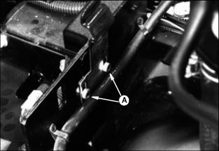
Adjusting PTO Clutch
PTO clutch is on engine crankshaft. Adjust clutch if blade stop time is more than 6 seconds. See Checking Blade Stop Time above.
IMPORTANT: Avoid damage! Turn each of the adjusting nuts same number of turns. You may want to mark brake plate and nuts before you adjust them to help keep track of turns. |
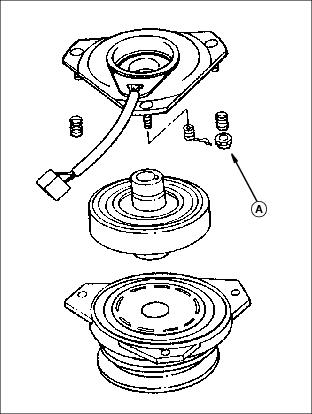
1. Tighten three nuts (A) 1/2 turn.
2. Check blade stop time. (See "Checking Mower Blade Stop Time" in Service Miscellaneous section.)
3. If stop time is more than 5 seconds, tighten three nuts 1/4 turn.
4. Start engine and listen for clutch scraping. If clutch is scraping, stop engine and loosen nuts 1/4 turn.