![]()
Introduction
Safety Signs
Controls
Operating Machine
Operating Mower Deck
Lawn Care
Replacement Parts
Service Machine Safely
Service Interval Chart
Service Engine
Service Transmission
Service Steering And Brakes
Service 48 & 54 Inch Mower Deck
Service 60 Inch Mower Deck
Avoid Injury From Contacting Blades
Removing And Installing The Belt Shield
Lubricating The Mower Deck Spindles
Lubricating The Mower Deck Belt Tensioner
Lubricating The Caster Wheel Bearings and Spindles
Lubricating The Lift Arm Pivot
Removing and Installing The Mower Deck Gearbox
Removing & Installing the Mower Deck Belt
Checking The Mower Deck Gearbox Oil Level
Changing the Mower Deck Gearbox Oil
Blade Installation and Removal
Service Electrical
Service Miscellaneous
Removing 48 & 54 Inch Mower Deck
Removing 60 Inch Mower Deck
Installing 48 & 54 Inch Mower Deck
Installing 60 Inch Mower Deck
Troubleshooting
Storing Machine
Assembly
Specifications
Warranty
John Deere Service Literature
John Deere Quality Statement
Copyright© Deere & Company

Service 60 Inch Mower Deck
Avoid Injury From Contacting Blades

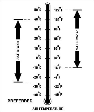
Gearbox Oil
Use the appropriate oil viscosity based on the air temperature ranges. Operating outside of these recommended oil air temperature ranges may cause premature gear case failure.
IMPORTANT: Avoid damage! ONLY use a quality oil in this gear case. Do not mix any other oils in this gear case. Do not use BIO-HY-GARD® in this gear case. |
The following John Deere gear case oil is PREFERRED:
· GL-5 GEAR LUBRICANT®-SAE 80W-90.
The following John Deere gear case oil is also recommended if above preferred oil is not available:
· GL-5 GEAR LUBRICANT®-SAE 85W-140.
Other gear case oils may be used if above recommended John Deere gear case oils are not available, provided they meet the following specification:
· API Service Classification GL-5.
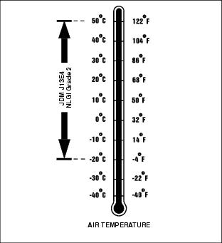
Grease
Use the following grease based on the air temperature range. Operating outside of the recommended grease air temperature range may cause premature failures.
IMPORTANT: Avoid damage! Do not mix any other greases in this application. Do not use any bio-grease in this application. |
The following John Deere grease is preferred:
· TY6341 Multi-Purpose Super Duty High-Temperature EP POLYUREA Grease. NLGI Grade 2.
Other greases may be used if above preferred John Deere grease is not available, provided they meet the following specification:
· John Deere Standard JDM J13E4, NLGI Grade 2.
Rotating the Mower Deck
Rotating the Mower Deck For Service
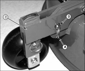
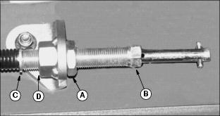
3. Remove retainer ring (A). Pull latch pin (B) out and rotate gauge wheel arm (C) up to service position.
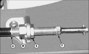
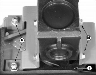
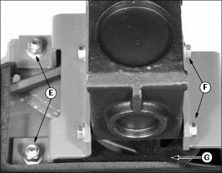
4. Remove the retaining ring (D) holding the rear hanger pin (E) to the adjustment plate (F). Lift up slightly on rear of mower deck and pull pin out of plate, taking note of which hole pin was removed from.
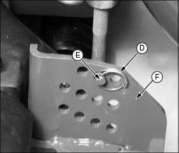
5. Remove retaining pin for other side of mower deck, and lower rear of deck to the ground.
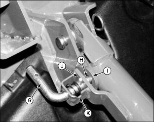
6. Rotate handle of service latch (G) forward so that lock pin (H) extends out to rest on bracket face (I).
7. Lift front of deck slightly to allow lock pin to drop into hole in lift arm.
Rotating Mower Deck For Operation
1. Pull service latch (G) out so that lock pin (H) is retracted from hole in lift arm (I).
2. Continue to pull service latch out while rotating handle rearward until lock pin (J) can be rotated into slot (K).
3. Insert rear hanger pin (E) into proper hole in adjustment plate (F) that matches cutting height setting of front caster wheels.
4. Install retaining ring (D) into pin (E). Repeat for rear hanger on other side of mower deck.
5. Lower mower deck to ground.
6. Rotate gauge wheel arm (C) down and lock with latch pin (B) and retainer ring (A).
Removing And Installing The Belt Shield

1. Rotate the mower deck for service. (See "Rotating the Mower Deck for Service" in this section.)
2. Remove the eight nuts (at arrows) holding belt shield to mower deck.
3. Lift the belt shield up off of the bolts.
4. Pull belt shield out from the mower deck under the left side lift arm.
5. Installation is the reverse of removal. Install belt shield from under left side lift arm. Make sure belt shield is installed onto all bolts around edge of shield before installing and tightening eight nuts.
6. Unlock mower deck service latch, attach rear hanger hardware, and lower deck to ground.
Lubricating The Mower Deck Spindles
1. Lubricate the three mower deck spindles through holes in belt shield (A, B, and C) using recommended grease. (See "Grease" in this section.)
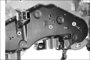
2. Pump grease gun 6-10 times for each spindle. A small "pop" may be heard as air is forced past the seal. Overgreasing will not cause damage, but grease will be thrown by blade, and is not recommended.
Lubricating The Mower Deck Belt Tensioner
1. Lubricate the mower deck belt tensioner arm pivot bushing through the hole (A) in the front of the belt shield.
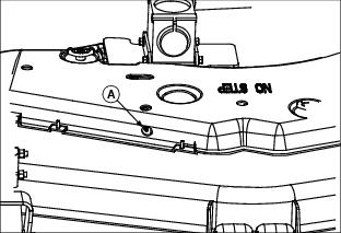
2. Pump the grease gun until grease seeps out of pivot bushing.
Lubricating The Caster Wheel Bearings and Spindles
1. Lubricate the left and right side caster wheel spindles at grease fittings (A) using recommended grease. (See "Grease" in this section.)

2. Pump grease gun until grease can be seen seeping out at bottom bearing (B).
3. Grease left and right side wheel bearings at grease fittings (C).
4. Pump grease gun until grease can be seen seeping out between wheel and caster wheel bracket (D).
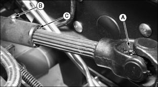
Lubricating The Driveline
2. Lift operator's seat platform and lock into highest position.
3. Turn PTO shaft by hand until grease fitting (A) on rear universal joint is exposed.
4. Pump grease gun until grease can be seen seeping out of all four universal joint seals. Clean excess grease from drive shaft.
5. Turn PTO shaft by hand until grease fitting (B) on mid-section of shaft is exposed.
6. Pump grease gun until grease can be see seeping out at splines (C) between front and rear PTO shafts.
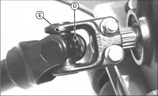
7. Rotate PTO drive shaft by hand until grease fitting (D) on front universal joint (at deck gearbox) is exposed.
8. Pump grease gun until grease can be seen seeping out of all four universal joint seals (E). Clean excess grease from drive shaft.
Lubricating The Lift Arm Pivot
1. Park Front Mower safely, with mower deck lowered.
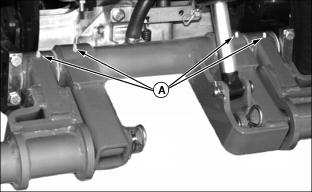
2. Lubricate four grease fittings on top of lift arm.
Removing and Installing The Mower Deck Gearbox
Gearbox Removal
2. Remove the belt shield. (See "Removing and Installing the Belt Shield" in this section.)
3. Lower mower deck. Stop engine.
4. Lift the seat platform to the highest position.
5. Locate PTO driveline (A) under seat platform. Disconnect PTO driveline from PTO gearbox shaft (B) by pulling forward on retainer ring (C) while pulling the universal yoke (D) off of the PTO gearbox shaft (B).

6. Push driveshaft forward to compress spline and lay driveshaft on frame.
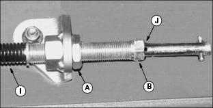
7. Loosen the mower deck belt tension by loosening locknut (E) and unscrewing the tension adjustment nut (F) counterclockwise until washer (G) contacts weld nut (H).
8. Remove the two locknuts (I) holding the mower deck gearbox bracket to the deck.

9. Remove the two cap screws (J) holding the gearbox to the left side bracket.
10. Lift gearbox and driveshaft assembly up from the deck, unhooking belt from the gearbox sheave (K) as assembly is removed.
Gearbox Installation
1. Route the mower deck drive belt around the gearbox sheave (L), while aligning the threaded holes in gearbox with cap screws (M) on left side gearbox bracket.
2. Install the right side gearbox bracket over bolts (N) and secure with lock nuts. Tighten nuts to 176 N·m (130 lb-ft).
3. Tighten gearbox mounting cap screws (M) to 99 N·m (73 lb-ft).
4. Connect the mower deck driveshaft coupler (O) to the vehicle's PTO gearbox shaft (P) by pulling the coupler ring (Q) forward while pushing the driveshaft rearward onto PTO gearbox drive shaft. Coupler ring should snap back to position shown when coupler is latched.

5. Tighten mower deck belt tensioner nut (R) until the spring (S) is completely compressed, and the drilled hole (T) on tension rod just begins to show.

6. Tighten tensioner lock nut (U).
7. Install the belt shields. (See "Removing and Installing the Belt Shield" in this section.)
Removing & Installing the Mower Deck Belt
Belt Removal
2. Remove the belt shield. (See "Removing and Installing the Belt Shield" in this section.)
4. Release mower deck belt tension by loosening tensioner locknut (A) and unscrewing tension adjuster (B) counterclockwise until washer (C) rests against weld-nut (D).
5. Remove the two locknuts (E) holding gearbox bracket to mower deck.
6. Remove two cap screws (F) holding gearbox to left side mounting bracket.
7. Lift gearbox bracket enough to remove mower deck belt out from the gearbox sheave (G).
8. Pull the mower deck belt out from the pulleys and off of the deck.
Belt Installation
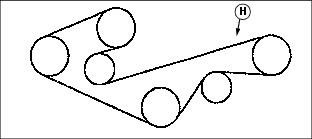
1. Route the new belt according the decal (H) mounted on the left rear of the deck.
2. Lift the mower deck gearbox enough to install the belt on the gearbox sheave.

3. Install the lock nuts (E) and cap screws (F) holding the gearbox and mounting plate to deck.
4. Turn belt tensioner nut (B) counterclockwise to tension belt until there are no spaces between the loops of the tensioning spring (I), and the drilled hole in the tension rod (J) just begins to show.
Checking The Mower Deck Gearbox Oil Level
1. Park Front Mower safely. Allow gearbox to cool.
2. Place a rag under check plugs (A & B) to catch oil.
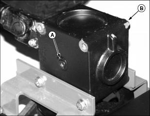
3. Remove the check plug (A) from one side of the mower deck gearbox.
4. Gearbox oil level should be up to the bottom of the check plug hole.
5. Pour or squirt oil through the opposite side check plug hole (B) until the oil runs out of hole (A).
6. Install plugs. Clean off spilled oil.
Changing the Mower Deck Gearbox Oil
1. Remove mower deck gearbox. (See "Removing and Installing the Mower Deck Gearbox" in this section.)
2. Remove the oil level check plugs (A) from both sides of the gearbox.
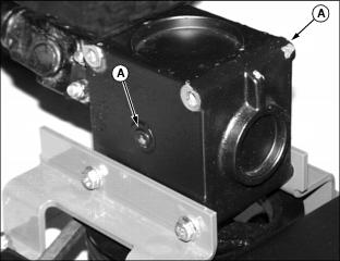
3. Turn the gearbox on it's side to drain it. After the oil has drained, turn the gearbox right side up.
4. Pour or squirt oil through the check plug hole until the oil runs out of the other hole.
5. Install the check plugs in the gearbox. Clean all excess oil from gearbox.
6. Install gearbox. (See "Removing and Installing the Mower Deck Gearbox" in this section.)
Replacing The Rollers
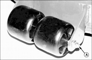
4. Pull the shaft out and remove the roller(s).
5. Install the new roller(s) on the shaft.
6. Install and tighten the lock nut.
Blade Installation and Removal
3. Rotate the mower deck for service. (See "Rotating the Mower Deck for Service" in this section.)
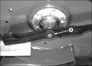
4. To remove a blade, insert wood block between end of blade to be removed and edge of deck. Turn blade mounting bolt (A) counterclockwise.
5. Inspect the blades for damage. Replace all damaged blades.
6. Sharpen dull blades. (See "Sharpening Blades" in this section.)
7. Clean blade, spindle, and hardware. Balance blade. (See "Balancing Blades" in this section.)
8. Install blade onto mower deck spindle with wings of blade facing up.
9. Install blade bolt and washer with the cupped-side of washer against the blade. Tighten blade bolt to 122 N·m (90 lb-ft). Repeat for other blades.
10. Unlock mower deck service latch and attach rear deck hangers. (See "Rotating the Mower Deck for Service" in this section.) Lower deck to ground.
Sharpening Blades
1. Sharpen blades with grinder, hand file, or electric blade sharpener.
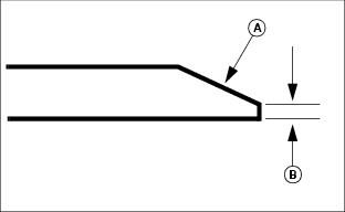
2. Keep original bevel of 30° (A) when grinding blade. Blade should have 0.40 mm (1/64 in.) cutting edge (B).
3. Balance the blade. See "Balancing Blades" in this section.
Balancing Blades
· Put the blade on a nail in a vise or wall. The heavy end of the blade will drop. Grind the bevel of the heavy end. Do not change the bevel.